Today designers and engineers have a lot of options when it comes to the many 3D printing technologies and materials available. In this article, we spotlight Multi Jet Fusion (MJF), HP’s proprietary 3D printing technology as a viable solution for many complex and industrial applications. We get into how it works, its benefits and whether it’s the right technology for your parts.
If you’re interested in learning more about the 3D printing technology available through Protolabs Network, head to our 3D printing service page.
What is Multi Jet Fusion (MJF) 3D printing?
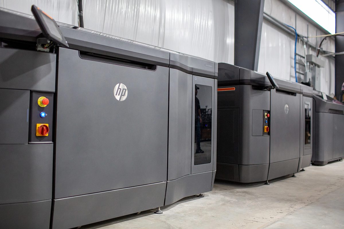
Multi Jet Fusion (MJF) is a 3D printing process that speedily produces accurate and finely detailed complex parts with powdered thermoplastics.
As it can consistently and quickly deliver parts with high tensile strength, fine feature resolution, and well-defined mechanical properties, MJF 3D printing services have rapidly become the go-to additive manufacturing (AM) solution for industrial applications. It’s commonly used to manufacture functional prototypes and end-use parts, parts that need consistent isotropic mechanical properties, and geometries that are organic and complex.
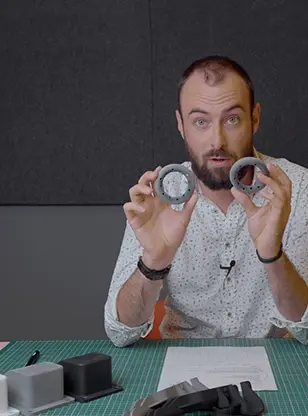
For a quick and detailed reference, watch our video all about MJF.
How was MJF developed?
First introduced to the market in 2016, MJF was developed by HP Additive, building on the company’s expertise in inkjet printing technology and precision mechanics. The development of MJF can be traced back to several decades earlier, though.
In the 1990s, additive manufacturing (AM) was beginning its transition away from only being used solely for research and development. Real-world, industrial applications in manufacturing were in sight. However, speed quickly became a key obstacle in this transition. Compared to injection molding or metal stamping, for instance, most 3D printers took a long time to produce parts.
One approach early adopters of 3D printing technology took to speed up production was to use “farms” or arrays of multiple machines. The idea was to print in higher quantities with the extra machining power. HP opted for a more integrated, automation-focused approach.
In their global AM hub in Barcelona, HP developed a system that built parts layer by layer in a large bed of powder material, with additional machinery attached for seamless post-processing. Similar to Selective Laser Sintering (SLS) and other powder bed fusion designs, this system evolved into current MJF technology.
How does Multi Jet Fusion work?
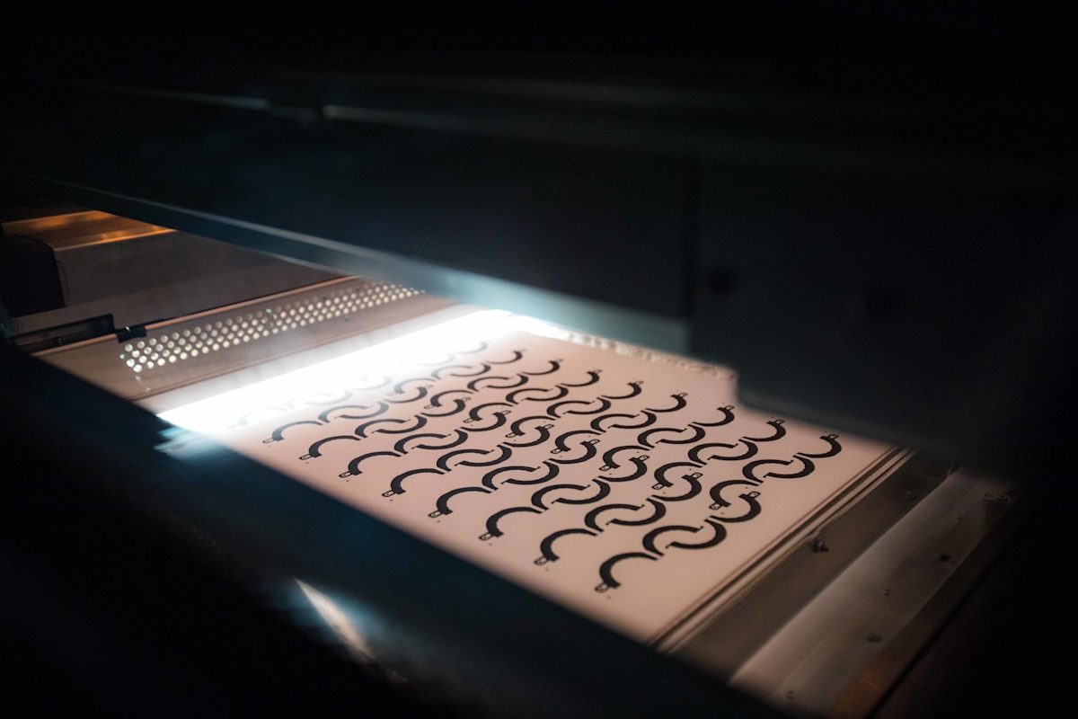
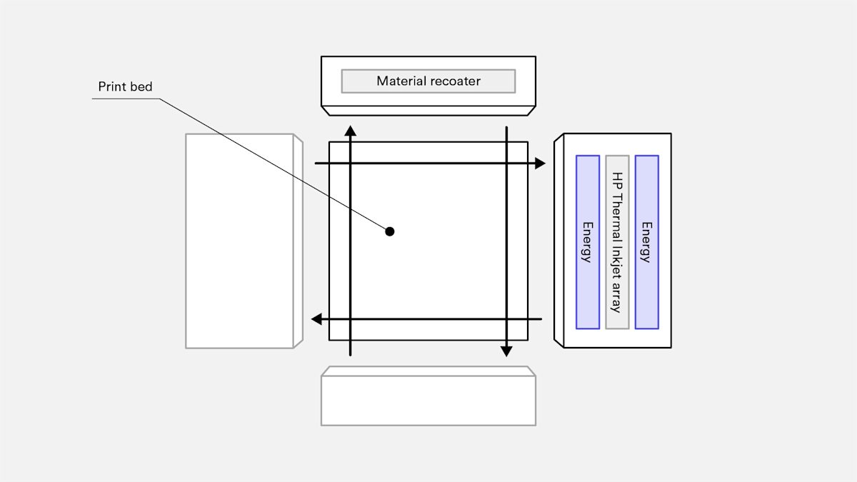
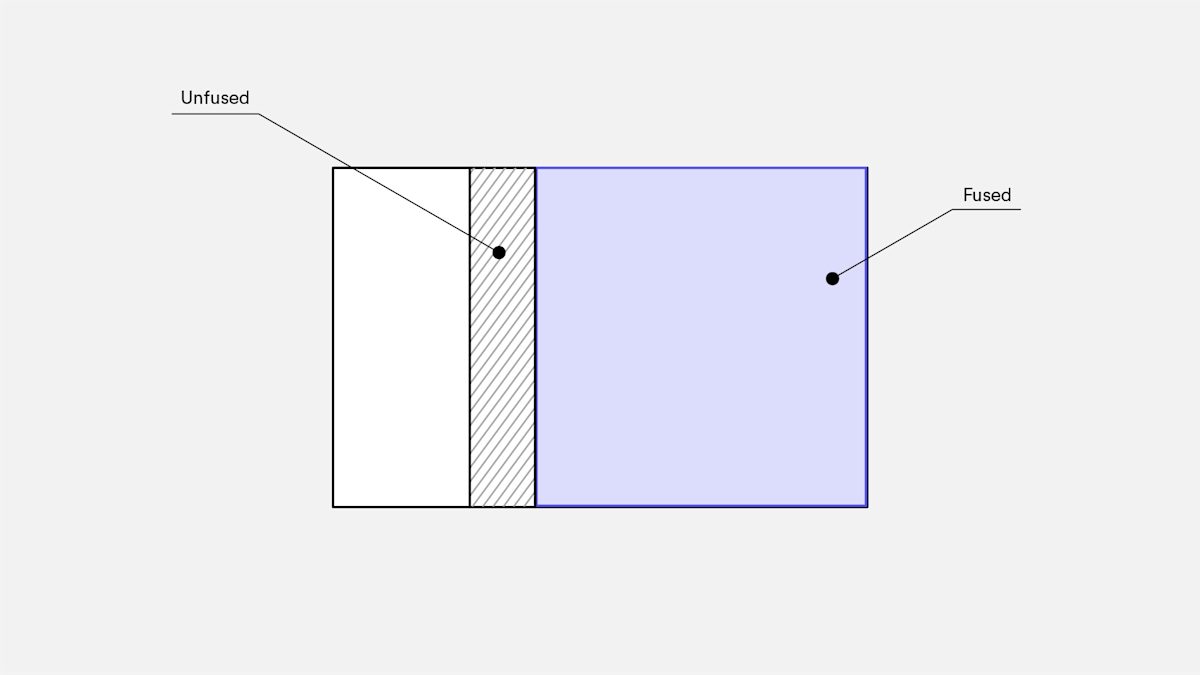
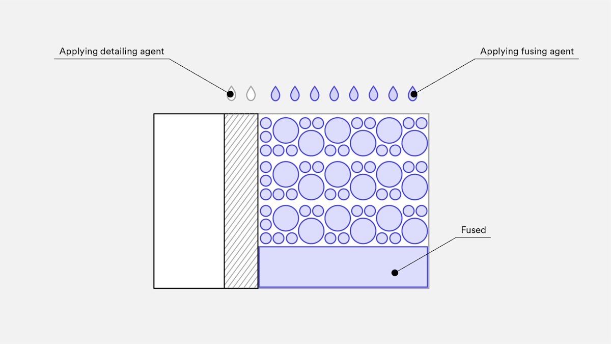
Using an inkjet array, MJF works by depositing fusing and detailing agents in a bed of powder material, then fusing them into a solid layer. The printer distributes more powder on top of the bed, and the process repeats layer by layer.
Here is a step-by-step of how MJF builds parts:
-
The moveable build unit is placed into the printer
-
The material recoater carriage moves across the build area, depositing a thin layer of the powder material
-
The printing and fusing carriage moves across the build area, preheating the powder to a specific temperature to provide material consistency
-
An array of inkjet nozzles fuses agents onto the powder bed in areas that correspond to the part’s geometry and properties
-
After each layer is finished, the build unit retracts to create space for the next layer of material to be deposited
-
This process repeats until the build is completed
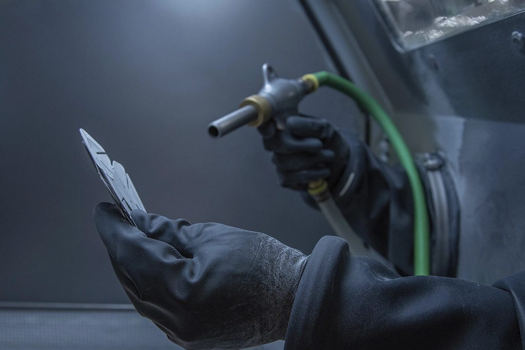
When the printing process finishes, the build unit contains the printed part and unfused powder. You use a separate processing station, attached to the moveable build unit, to cool and unpack the part, and recover excess powder for later use. Bead blasting helps to remove any of the remaining powder and allows you to move on to more cosmetic steps.
What materials does MJF use?
In general, you can split the materials used for MJF into rigid plastics and flexible plastics. Rigid plastics include Nylon PA11, Nylon PA12 and PP, while flexible plastics include Estane 3D TPU M95A. HP’s system focuses mainly on polyamide materials, developed by HP and its partners.
Here is a list of the MJF 3D printing materials available on the Protolabs Network platform.
| Material | Description |
|---|---|
| HP PA 12 (Nylon 12) | Nylon 12 is a robust thermoplastic with all-around excellent physical properties and chemical resistance, ideal for functional prototypes and end-use applications. |
| Glass-filled HP PA 12 | Glass-filled nylon is reinforced with glass bead and creates parts with higher stiffness and thermal stability than standard nylon. |
How does MJF post-processing work?
Similar to other manufacturing processes, further processing is required before a part is ready for prototyping or end-use applications. However, post-processing with MJF is relatively light compared to other AM technologies.
When you finish a print job, you are left with a build unit filled with a three-dimensional bed of unfused powder, with the part buried inside.
These are the main steps in MJF post-processing:
-
Cooling: This takes place within the build unit, though HP offers module units for natural cooling, so the build unit can be used for a new print without having to wait for the powder and part to cool.
-
Recovering unfused powder: Once the build unit has cooled down, move it to the processing station and vacuum the unfused powder into a container for later use.
-
Bead blasting: Remove any remaining powder with bead blasting, air blasting or water blasting. You can do this manually or automatically, using a tumbler, ultrasonic cleaner or vibratory finishing machine.
After removing all residual powder material, you may have to go through more post-processing. This depends on the part. For instance, consider the post-processing required for casting processes. You may need to do more machining for features like mating surfaces, bores, tolerances exceeding the capabilities of MJF and internal threads. As well, meeting specific technical requirements may require you to sand the part by hand.
What are the advantages of MJF?
If you’re looking to create functional prototypes and relatively small production runs of end-use parts, then MJF should be your go-to solution. MJF is excellent for building much stronger parts than what SLS can produce. Parts built with MJF have tensile strengths of maximum XY and Z 48 MPa/6,960 psi with the ASTM D638 method.
As well, MJF is really good at producing mechanical properties in every direction of your part’s geometry. So if you’re making parts with complex, multifaceted designs that also come with smaller features that need to be sturdy, then MJF is the most viable option.
MJF produces functional parts for end-use without a lot of post-production required. Compared to other AM technologies, it’s faster and offers more robust automation, meaning far shorter lead times and high-quality surfaces with minimal human intervention.
To achieve its speediness, MJF consistently scans the surface of the part it’s printing every pass, even if you’re using it to print multiple parts at once. This provides quicker build speeds in comparison to other technologies, even with larger quantities of parts.
Why is MJF ideal for manufacturing end-use parts?
MJF distinguishes itself from other additive manufacturing processes as it’s designed to produce higher volumes of parts with great complexity, detail and structural integrity. MJF is a popular solution for manufacturing precise and durable electronic component housings, mechanical assemblies, enclosures, and jigs and fixtures.
In current MJF machines, the build unit is a rolling cart that’s attached to an included processing station. Once a part is complete, all you have to do is move the powder bed to the processing station to remove all the excess powder. Post-processing can be done in bulk, depending on the technical requirements of the part, and more often than not, there is minimal need for hand finishing. This makes it well suited for higher volume production runs of functional parts.
The powder bed system itself eliminates the need for supports, with parts being nested efficiently in the build area. After the part is complete, you can also use the unused powder again for future print production runs.
MJF vs SLS 3D printing: what’s the difference?
While selective laser sintering (SLS) is quite similar to MJF, the two technologies have a few key differences. SLS printers also deposit powder material in a build area layer by layer, however, the machine fuses materials by sintering powder particles together and to the underlying layer of the part with a laser.
You can modulate the laser’s power to alter the part’s material properties, though the parameters of this feature are limited. HP has a broad selection of chemical agents, providing more opportunities to alter the properties of each voxel of the part.
MJF vs. Injection Molding: which is better for your application?
MJF is not only a powerhouse compared to other AM technologies - it’s also a viable alternative to injection molding. With injection molding, you have to pay for the mold itself and undertake a lot of DFM analysis before producing the part. It’s also restrictive in terms of part geometry and the lead time is significantly longer, considering the time it takes to produce the mold and other processing steps.
By contrast, MJF allows for more expansive design freedom, with greatly reduced lead times. You can also make design changes rapidly with MJF, as you don’t have to rely on the mold. If you’re about to do a production run with injection molding, definitely consider MJF, especially if you are hoping to create high volumes of small to medium sides parts with complex geometries.
In general, MJF is preferable for creating prototypes and for small and medium production runs. You can print prototypes in a few days, and any MJF-printed part will have mechanical properties of the same caliber as injection molding.
What are examples of Multi Jet Fusion in action?
One impressive use case for MJF comes from CNC Würfel, a manufacturing and process automation specialist for the automotive industry and medical technology, among other sectors. In 2017, CNC Würfel replaced milling machines and lathes with 3D printing for many of their components. This drastically cut production times and allowed for more time spent on testing prototypes.
This proved particularly effective in producing the company’s gripper adapter, a part used on conveyor belts that requires several complex parts and gripping systems. Traditional processes resulted in eight to ten weeks of lead time, and required extensive human knowledge and intervention that sometimes damaged the part.
To cut out many of the complexities of manufacturing the gripper adapter, CNC Würfel opted instead to 3D print it using MJF. This immediately proved beneficial, especially as it cut production times down from two months to easily under a week. Using MJF also saved the company a huge amount of money. The cost reduction for printing the part ended up being 95% compared to traditional manufacturing. As an additional benefit, the printed part was 84% lighter, yet still durable enough to take on its tasks.
Another strong use case for MJF is HP’s Z 3D Camera, developed to simplify real-time capture and visualization of documents and other objects. Prior to the invention of MJF, HP built the camera out of three separate injection molded parts, which led to weeks of prototyping and incurred costs for each part.
Switching to MJF to produce the camera sped up production, as new technology allowed HP to print a single assemblage as opposed to three parts. According to HP, this pivot also reduced the price per part from $2.42 to $0.36, and transformed the prototyping duration from weeks to days. As well, the design freedom that comes with MJF gave HP the opportunity to optimize the orientation of the camera, which raised the quality of the end product.
MJF: Handy tips and tricks
Here are some hands-on best practices for getting the most out of MJF technology.
-
Reinforce thin-walled or large, flat surfaces with ribs or gussets, and surround holes with raised bosses when possible.
-
Be aware that raised text and cosmetic features smaller than 0.5 mm might not survive secondary post-processing. Check the DFM analysis in your part quote for these details.
-
The walls of your part should be between 2.5 and 12.7 mm thick. Going above or below this may affect the tolerances of your part.
-
Make sure to clearly identify cosmetic surfaces so the manufacturer avoids features like stair-stepping on oblique angles of the part.
Frequently asked questions
What are the benefits of MJF?
MJF lets you produce large quantities of unique parts without relying on arrays of multiple printers. It can also replace costly casting or molding work, and current HP systems include an attached bulk post-processing station, which minimizes hand finishing.
What are the drawbacks of MJF?
MJF is more costly than modular printing technologies like FDM, though the quality is higher and more consistent for industrial uses.
Are MJF 3D printed parts water resistant?
PA 12 Nylon is one of the only water-resistant 3D printing materials. Walls of an MJF part have to be 1 mm thick to be water-resistant, while wall thicknesses over 4 mm make parts watertight. MJF parts are also chemically resistant to greases, alkalies, oils and aliphatic hydrocarbons.
What is the dimensional accuracy of MJF?
The dimensional accuracy of MJF is ± 0.3% with a lower limit of ± 0.3 mm (0.012'').
What is the maximum build size of MJF?
With Protolabs Network, the maximum build size of MJF parts is 380 x 285 x 380 mm (14.9'' x 11.2'' x 14.9'').
What are the smallest features MJF can print?
The minimum feature size MJF can print is 0.5 mm (0.02 in). MJF’s print layers are 80 microns (0.0003 in) thick, meaning it can produce very fine surface details.
