PROTOLABS NETWORK - MANUFACTURING STANDARDS
Last updated: 12 Jan 2024
Version: 2.1
A detailed description of our manufacturing capabilities can be found in our capabilities PDF. Any order placed should take the following manufacturing limitations in mind, unless otherwise agreed between the parties under specific circumstances.
3D printing
All surfaces will have a consistent visual appearance. FDM and SLA parts will have the support structures removed and will be cleaned of all excess support/build material. All parts will be cleaned and have excess powders and materials removed.
The acceptable accuracy of parts varies by technology and is stated as:
| Material | Dimensional accuracy |
|---|---|
| Prototyping FDM: | ± 0.5% with a lower limit of ± 0.5 mm (± 0.02") |
| Industrial FDM: | ± 0.3% with a lower limit: ± 0.3 mm (±0.012" in) |
| Prototyping SLA/DLP: | ± 0.3% with a lower limit of ± 0.3 mm (± 0.012") |
| SLS/MJF: | ± 0.3% with a lower limit of ± 0.3 mm (± 0.012") |
| Industrial SLA: | ± 0.2% with a lower limit of ± 0.13 mm (± 0.005") |
You can find more detailed information on our SLA, SLS, FDM, and MJF service pages. If you need DMLS or PolyJet, our parent company, Protolabs offers those services.
CNC machining
We offer CNC milling and CNC turning. If not otherwise specified on the technical drawing, all parts will be machined to ISO 2768 tolerance standards:
| Limits for nominal size | Plastics (ISO 2768- m) | Metals (ISO 2768- f) |
|---|---|---|
| 0.5mm* to 3mm | ±0.1mm | ±0.05mm |
| Over 3mm to 6mm | ±0.1mm | ±0.05mm |
| Over 6mm to 30mm | ±0.2mm | ±0.1mm |
| Over 30mm to 120mm | ±0.3mm | ±0.15mm |
| Over 120mm to 400mm | ±0.5mm | ±0.2mm |
| Over 400mm to 1000mm | ±0.8mm | ±0.3mm |
| Over 1000mm to 2000mm | ±1.2mm | ±0.5mm |
| Over 2000mm to 4000mm | ±2mm |
*Customers are asked to clearly indicate tolerances for nominal sizes below 0.5mm on their technical drawings.
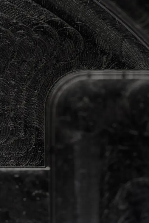
Standard order surface finish shall be referred to as “as machined” and requires a Ra 3.2μm / Ra 126μin finish. Minor tool marks, machining marks and light surface scratches are visible. All sharp edges and burrs will be removed. If any form of threads (internal or external), any non-standard tolerances or any non-standard surface finish are required, these must be clearly indicated in a technical drawing.
For powder coating, unless the desired color is “black”, this must be clearly communicated in the form of a RAL or PANTONE number. The manufacturer will match it at the best of his ability. Perfect color match cannot be guaranteed.
For anodizing type II, we offer standard colors to our checkout, including clear, black, red, blue, orange and gold, on an as-machined, brushed, or bead blasted surface.
You can find more information on how these colors match up with RAL/PANTONE equivalents on our aluminum anodizing services page.
For anodizing type III, we offer two color options, clear and black, on as-machined primary finish or bead blasted surfaces.
For more information on surface preparation, color equivalents, glossiness and visual appearance expectations, visit our aluminum anodizing services page.
Injection molding
Standard core & cavity surface finish will have minimal machining marks and will be smoothed to the manufacturer’s discretion. In case a different finish is required, this must be specified clearly in the form of an SPI finishing standard.
Part shrinkage will be determined by the manufacturer and the molds will be CNC machined to standard tolerances of ± 0.125 mm (± 0.005") after adjusting for part shrinkage. Unless otherwise noted, standard tolerance of ± 0.250 mm (0.010") will be held for each manufactured part. Part-to-part repeatability will typically be < 0.100 mm (0.004"). Any tolerances tighter than ± 0.125 mm (± 0.005") will be a best effort. Protolabs Network will share a DFM report to align on draft details, parting lines, gates, exectors, and other part specifications. If alterations are required after first article inspection to achieve tighter tolerances, additional charges may apply. Design changes, such as draft and increased or decreased wall thickness may be required to improve moldability and may affect pricing.
Unless otherwise specified, all quotes are based on the assumption that standard injection molding equipment will be used. If special tooling configurations are required, they must be expressed during the quoting process.
Sheet metal fabrication
We offer laser cutting and bending, with our sheet metal fabrication service, with a variety of materials including aluminum, stainless steel, and copper materials.
Tolerances for sheet metal fabrication
The table below summarizes the standard tolerances of the parts produced by our certified manufacturing partners.
| Feature | Tolerance |
|---|---|
| Cutting feature | ±.00787’’ (0.2mm) |
| Bend angle | ± 1.0° |
| Bend to edge | ± 0.010” (0.254mm) |
Questions
Questions regarding the specifications in this document should be directed to supply@protolabs.com.
